Our festive opening times Find Out More

Choose your charger

Our festive opening times Find Out More

Choose your charger
Back

Installation guide

Installation procedure

Warning & Safety Notes:
Failure to follow these instructions may cause equipment damage or serious injury.

  • Qualified installer: The Indra charger must be installed by a fully qualified and competent professional, following the latest wiring regulations (BS7671)
  • Power isolation: Ensure the electrical power supply is safely turned off before starting installation or maintenance.
  • O-PEN Protection Device: Do NOT use an upstream O-PEN protection device with the Indra Smart Charger. Doing so will VOID the warranty
  • Installation location: Install the charger in a location that is structurally sound, free from excessive vibration, dust, or material build-up, which could interfere with normal operation.

Switchgear requirements:

Install a Type A, double-pole, 30mA RCD upstream of the charger.

Recommendations:
40A Overcurrent protection.
Type 2 Surge Protection Device (SPD) to protect against power surges.

Required tools and equipment

To complete the installation, you will need the following:

  1. Smartphone or tablet – To operate the "Installer App."
  2. UK EV Charging Station Test Adaptor Kit
  3. T-20 screwdriver
  4. IDC punch-down tool
  5. CAT5E cable (required if hardwiring the charger to the internet)
  6. RJ45 male connectors (required if hardwiring the charger to the internet)
  7. RJ45 crimping tool (required if hardwiring the charger to the internet)

Additionally, have your standard installation tools on hand.

Step 1: Charger layouts

Smart LUX
Smart PRO
Smart LUX

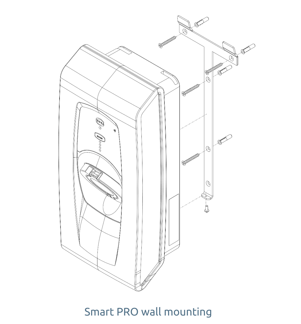
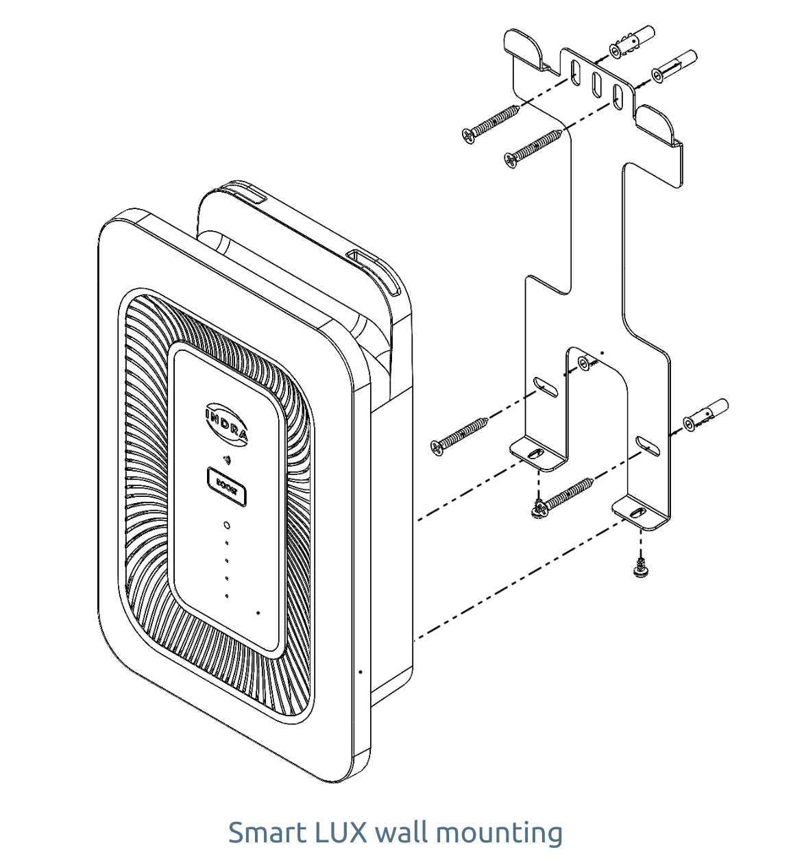
Choose a suitable location:

  • Select a wall space that allows convenient access for charging while minimizing potential trip hazards and risk of impact damage.
  • Ensure the surface is flat and sturdy enough to support the charger.

Attach the mounting bracket:

  • Using the 4 screws provided, securely fix the mounting bracket to the wall.

Mount the charger:

  • Align the charger with the mounting bracket.
  • Slide the top two bracket receptacles over the corresponding points on the bracket.
  • Gently lower the charger until it sits flush against the bracket.

Secure the charger:

  • Use the provided security screw(s) to firmly secure the charger to the bracket, ensuring it is stable and properly attached.
Video: How to mount an Indra charger to the wall

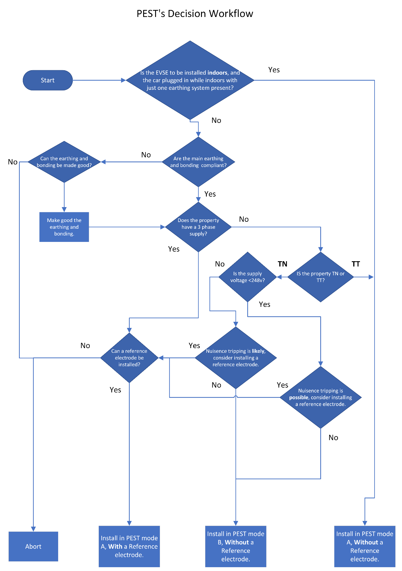
The charger is pre-configured in PEST Mode B, ensuring compliance with BS 7671:2018 Amendment 3, Regulation 722.411.4.1, Indent (iv).

How it works:

In this mode the charger will monitor the for deviation outside of the acceptable range (253V – 207V).

  • If the supply voltage goes outside this range, the charger automatically stops charging.
  • Charging will resume once the voltage returns to the acceptable range.

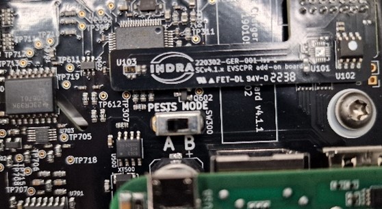
This configuration is suitable for the majority of installations.

Need a different configuration?

Setting the charger to PEST mode A is a way of telling the charger that O-PEN faults are being managed elsewhere. E.g. the installation is on TT, or the car and charger can only be inside when charging.
PEST mode A exists for when the other options are not suitable and is designed around compliance with regulation 722.411.4.1 indent (iii) BS7671 AMD 3.

This method removes the need to measure supply voltage to identify O-PEN faults, thus mitigating issues with variable supply voltages.

It uses a voltage reference in the ground and compares its voltage to that of the CPC of the installation. If the voltage between the two goes over 30V the charger disconnects from the car and will not offer again until the voltage drops back within range.

Reference Electrode:
A reference is a voltage reference only, it is NOT a fault return path and is a TT electrode cut down to 300mm and should achieve a resistance of <600Ω. This enables the reference to be stable when the ground dries out in the summer.

The reference should be connected to the “RefE” connection in the charger.

• Voltage Reference ONLY
• 300mm long
• Minimal risk of striking buried services
• <600Ω
• Solar PV Cable

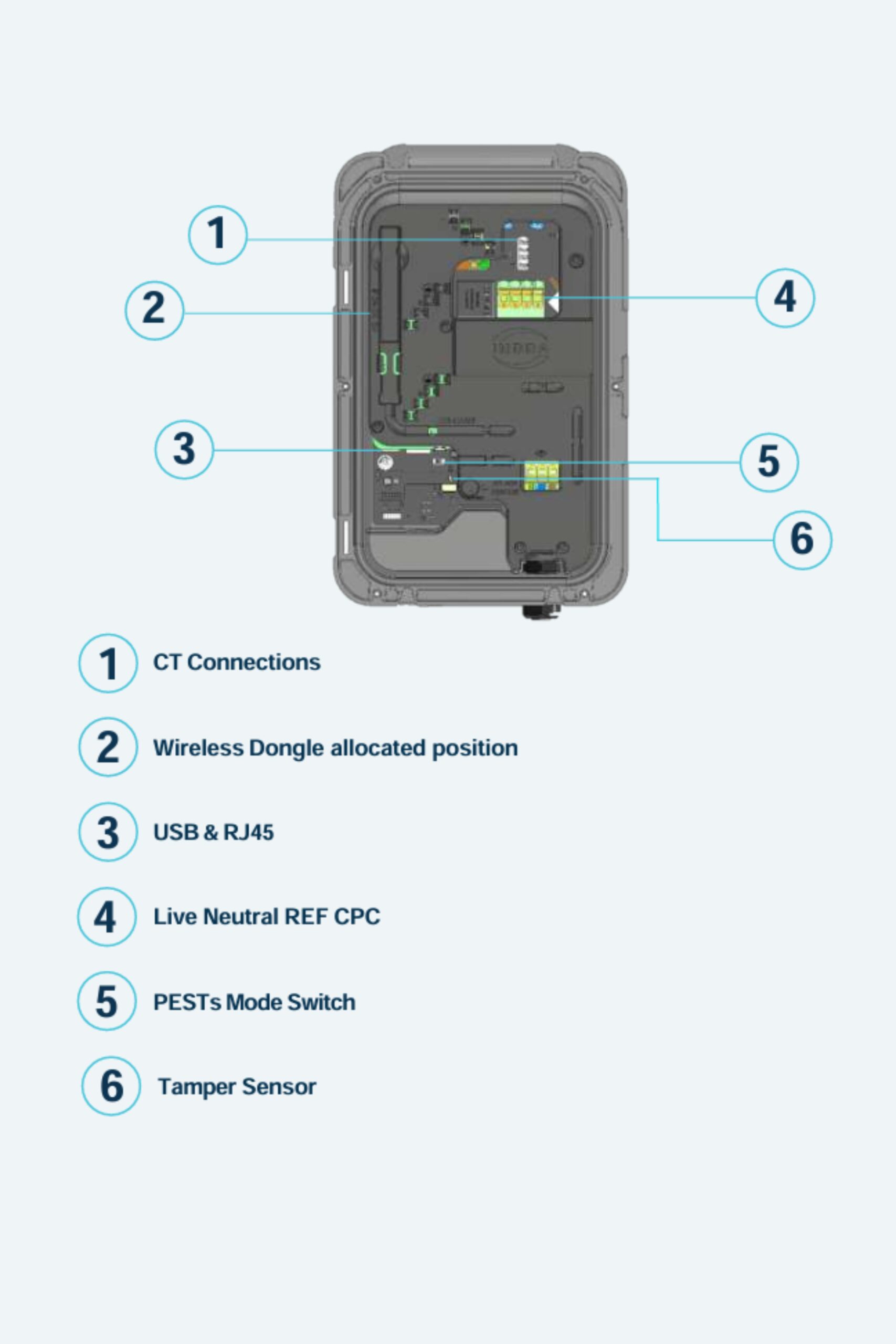
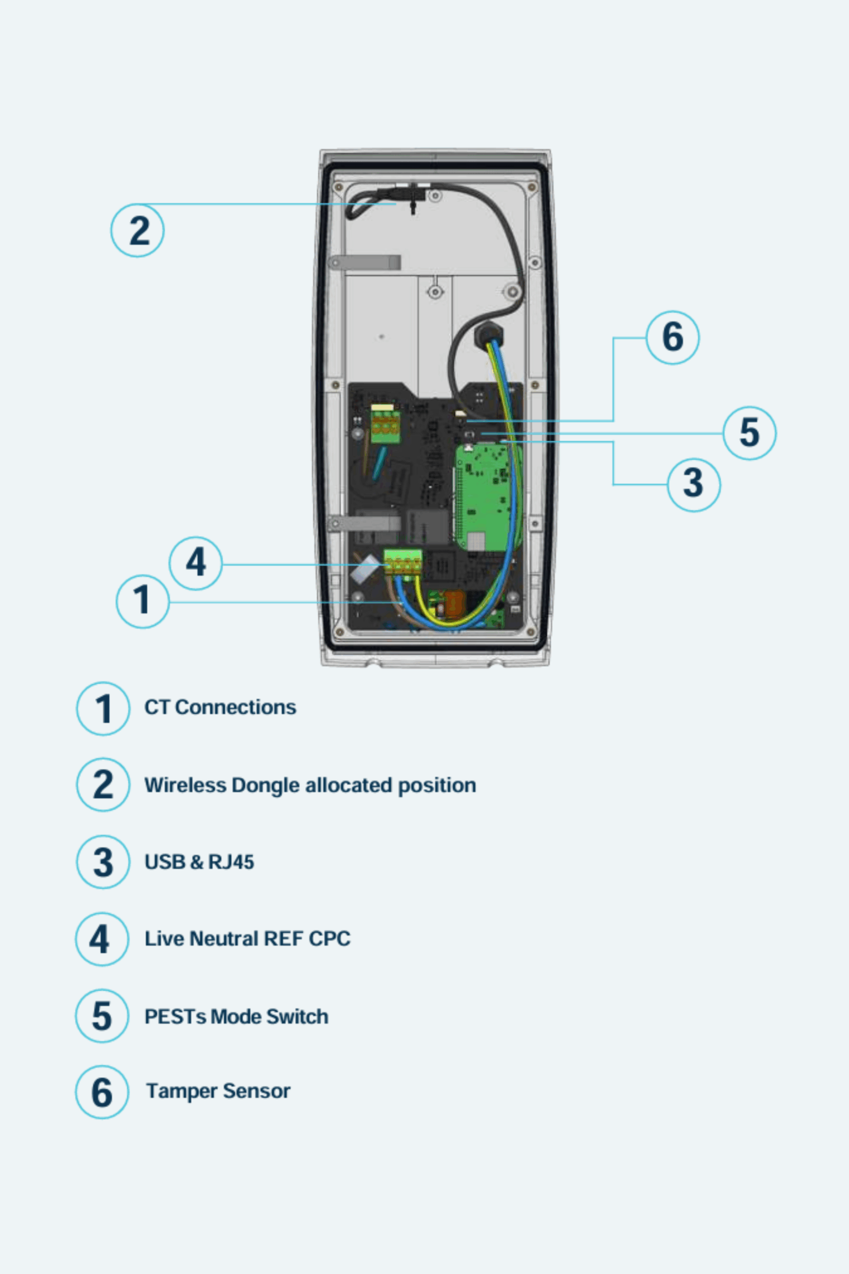
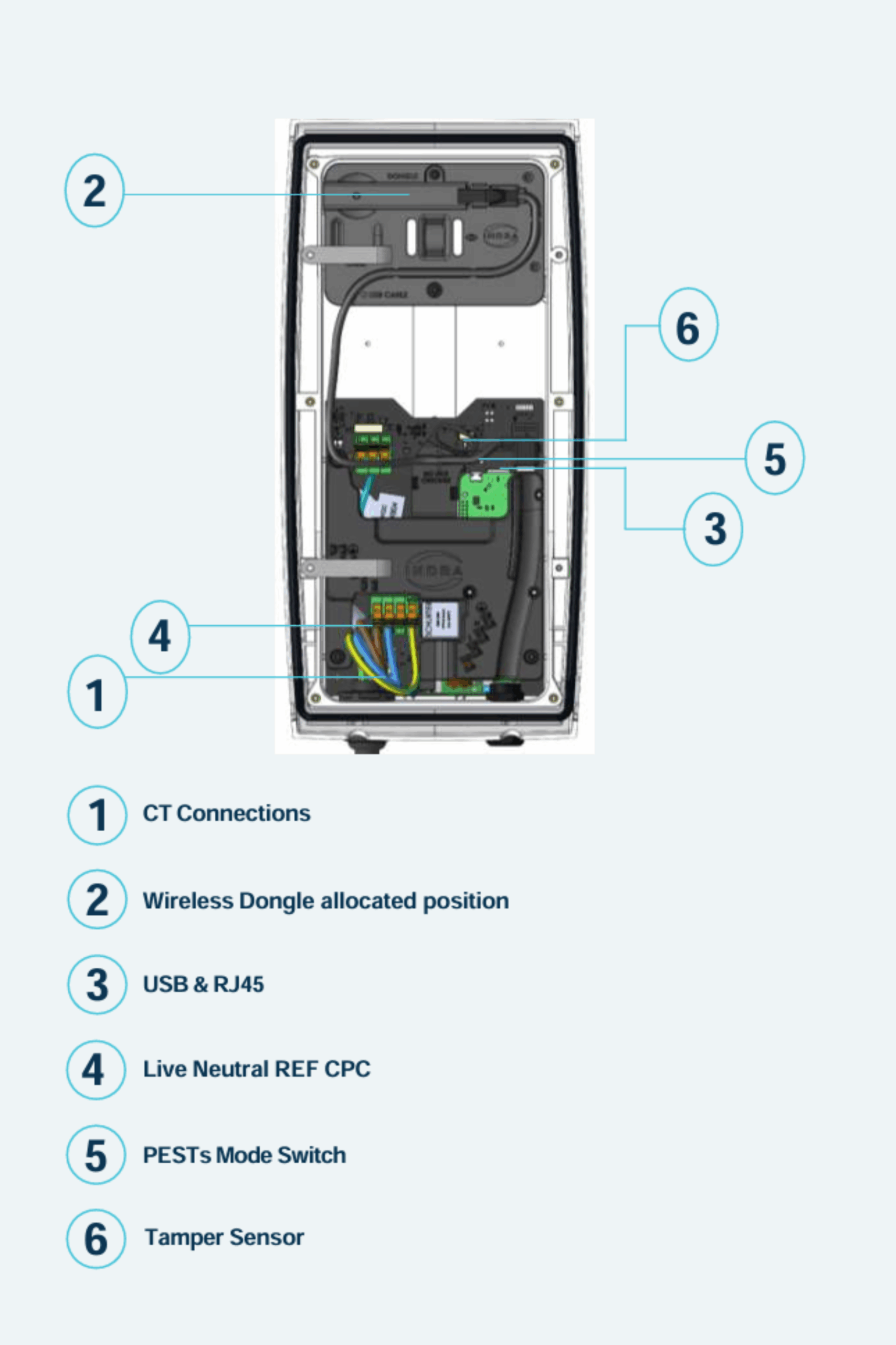
If the charger needs to use Load Curtailment or Solar Mode features, an external CT (Current Transformer) must be installed. A CT is included in the box. This allows the charger to monitor the total electrical demand of the installation and the total export from any micro-generation system.
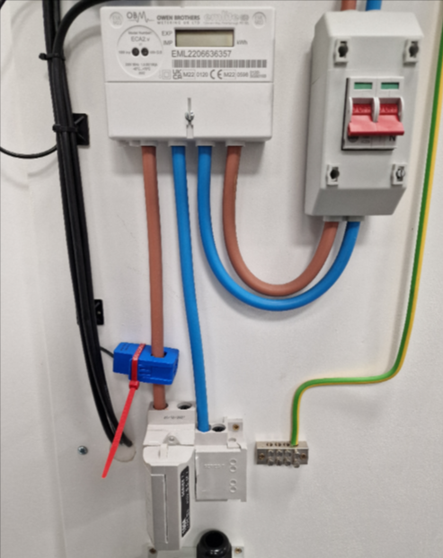
1. Position the CT:

The CT should be clipped onto the incoming live supply cable before any junctions. With the arrows facing the grid (see photo).

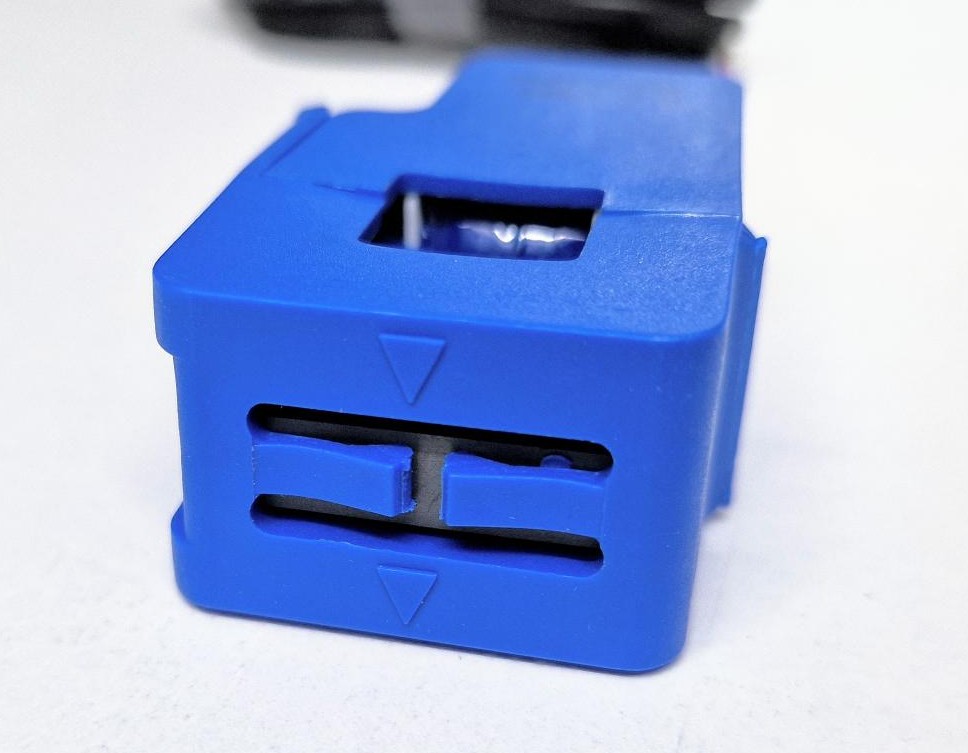
2. Connect the CT Clamp wires:

Use the provided jelly crimps to join the CT clamp wire to the Blue/Blue White pair of your data cable.

Data cable wireCT clamp wire
BlueRed
Blue & whiteWhite

3. Terminate the data cable:

Using an IDC punch-down tool, terminate the Blue/Blue White wires into the CT connector.

Note: other data cable colours may be used but must terminate into the BE, BE/WE connection inside the charger.
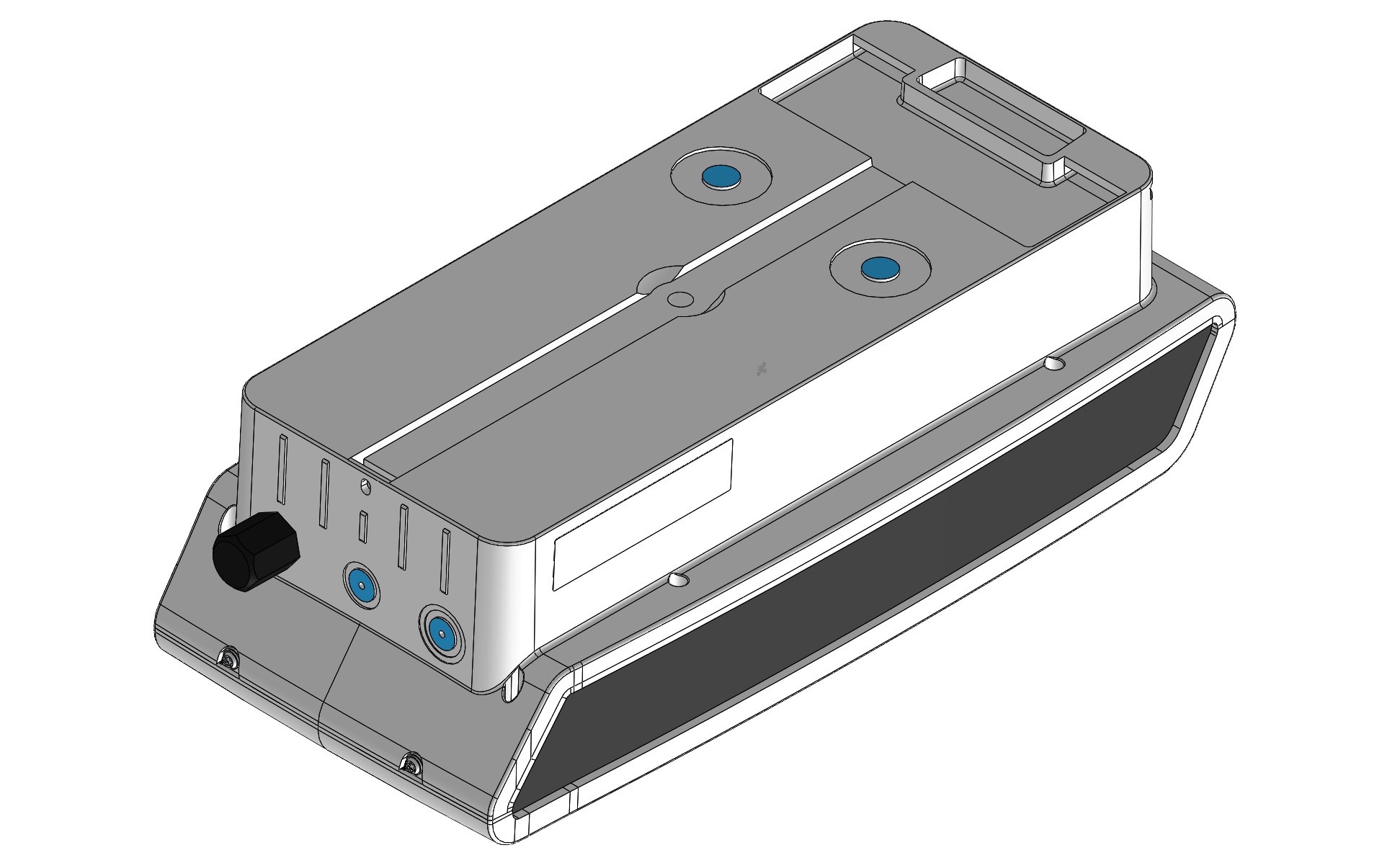
Video: How to install the CT clamp
Duration: 1 min 56 secs

1. Cable entry:

Cable entry can be made via the bottom or the rear of the charger through the marked entry points.

A minimum IP rating of IP65 MUST be maintained.

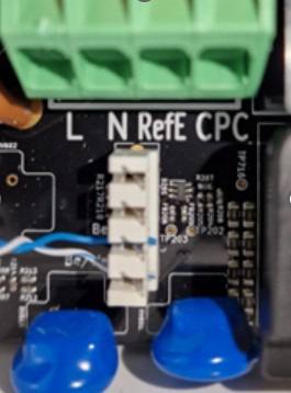
2. Connecting the supply to the charger:

Connect the supply to the charger as follows:

Supply cableCharger connections
Brown (Live)L
Blue (Neutral)N
N/aRefE
Green/Yellow (CPC)CPC

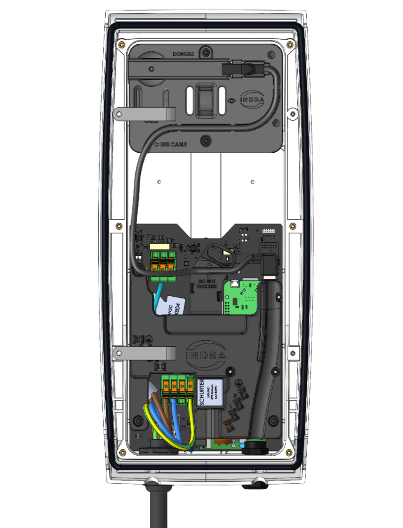
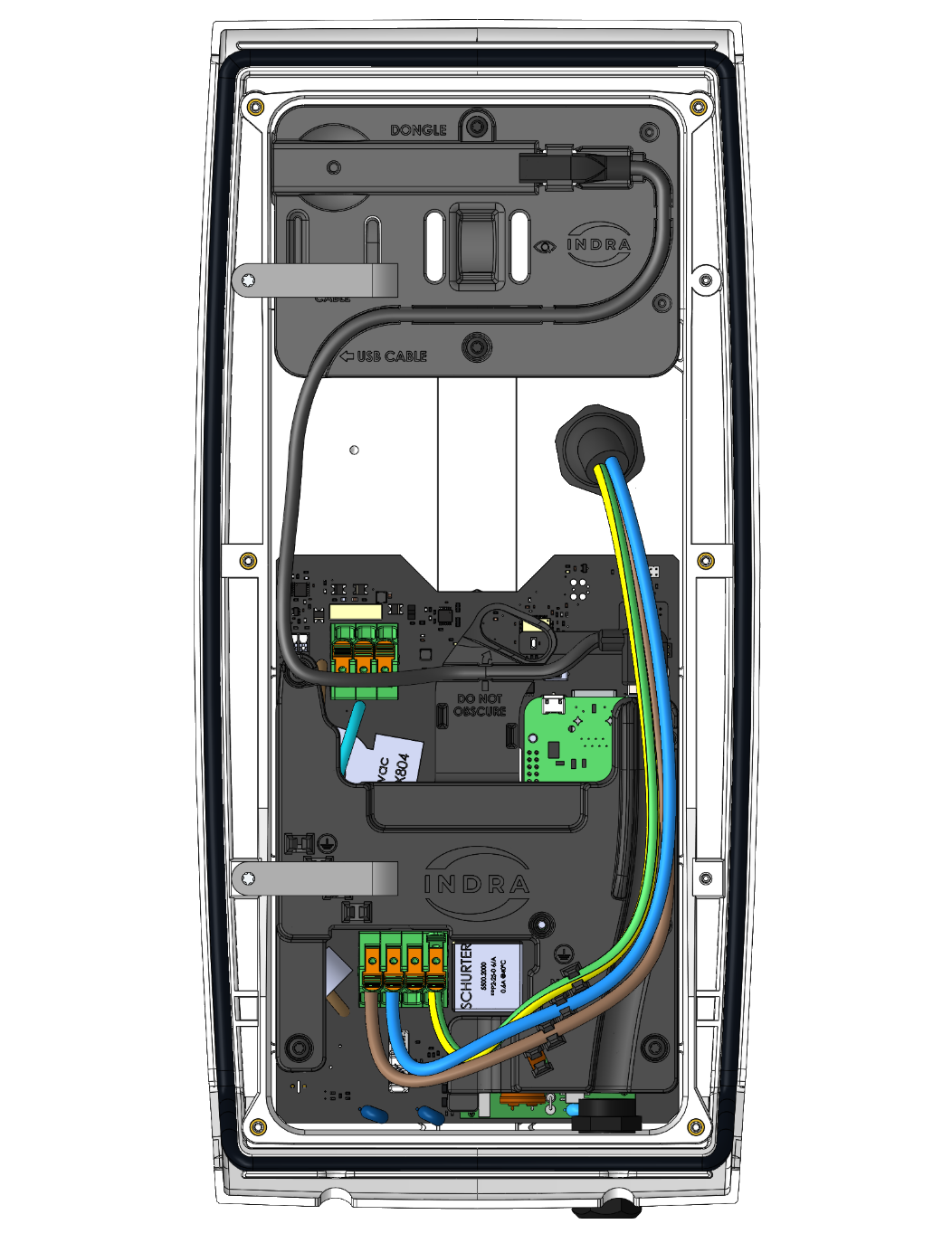
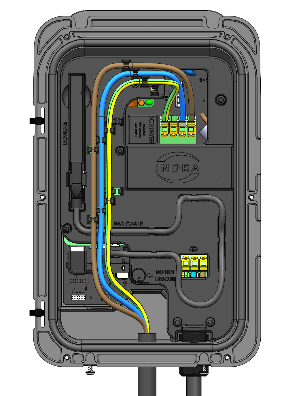
Ensure there is no tension on the electrical connections by dressing the cables appropriately.

Video: Connecting the supply to the charger
Duration: 44 secs

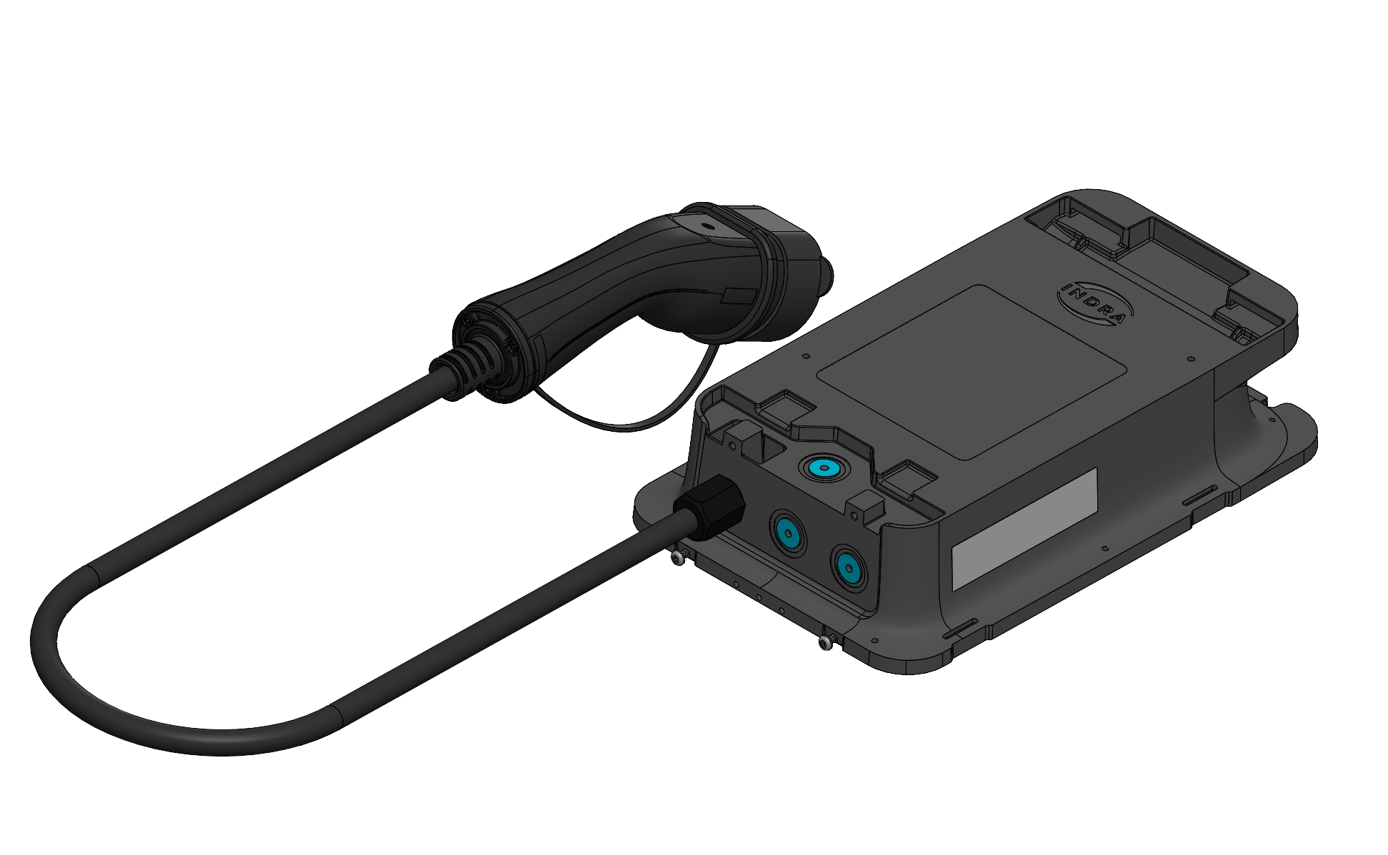
If you are using a wireless connectivity method, fit the appropriate dongle into the USB extension as shown below.

Note: If using a cellular dongle, record the WCD number before fitting.

Video: How to insert the dongle
Duration: 6 secs

Attach the front panel:

Use the 6 provided T20 screws to secure the front of the charger in place.

Install the fascia:

Hook the fascia to the top of the charger, hinge down and secure with T20 screw(s).

Video: How to seal the unit
Duration: 1 minute 30 secs

To perform electrical testing on the charging circuit, you will need a Multifunction Tester (MFT) capable of testing at 6mA or less*. Click on 'Steps to perform the test' for more information.

  1. Connect the MFT
    • Use an EVSE test adapter to connect your MFT to the charger.
  2. Set the EVSE Test Adapter
    • Switch the EVSE test adapter mode to Mode B.
  3. Activate the Charger
    • Press the boost button on the charger to initiate power.
  4. Switch to Mode C
    • Change the EVSE test adapter mode to Mode C.
  5. Conduct Testing
    • Once the adapter shows power, you can proceed with your testing.
    • Note: You do not need to wait for the charger to come online before testing.

Additional Notes:

  • Wait for the charger to complete its boot cycle before starting the test.
  • If your MFT cannot test at 6mA or less, you will need to calculate Zs instead. Using an incompatible tester may trigger the charger’s built-in DC leakage protection.

Dummy load testing allows you to perform a full functional test of the charger without an EV being present.

Equipment Required:

  • EVSE Test Adapter
  • Appliance with a 3-pin plug

Steps to Perform Dummy Load Testing:

  1. Connect Equipment
    • Attach the EVSE Test Adapter to the charger.
    • Plug the appliance into the load side of the EVSE Test Adapter.
  2. Set the EVSE Test Adapter
    • Switch the EVSE Test Adapter to Mode B.
  3. Activate the Charger
    • Press the boost button on the charger* to activate power.
  4. Switch to Mode C
    • Change the EVSE Test Adapter to Mode C.
  5. Verify the Test
    • The appliance should power on.
    • The charger’s status LEDs will display a scrolling down pattern, indicating successful functionality.

Additional Notes:

  • *Alternatively, you can use the customer’s app to set a charging schedule as part of the handover demonstration instead of pressing the boost button.
Random Delay is not active on a boost charge.
Video: How to perform an electrical test
Duration: 1 minute 3 secs

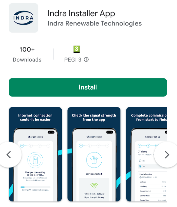
To connect and commission your charger, you will use the Indra Installer App:

If you already have the App and log in details for it:

  • Open the App

If you don't already have the App:

  • Search for "Indra Installer App" in the App Store (for iOS devices) or Google Play (for Android devices).

Alternatively, click the button below to be redirected to the appropriate app store for your device.

Download the Indra Installer App

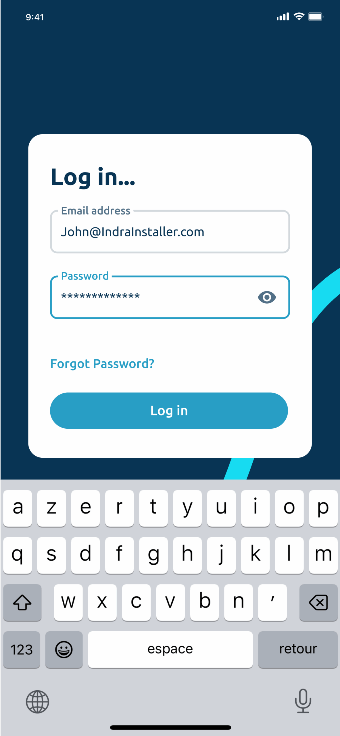
If you have logged in before:

  • Use your registered email and password to access the Indra Installer App.

If this is your first time using the App:

  • After completing and submitting the form in Step 1, check your email inbox. You should have received an email containing your password. Use these details to log in.

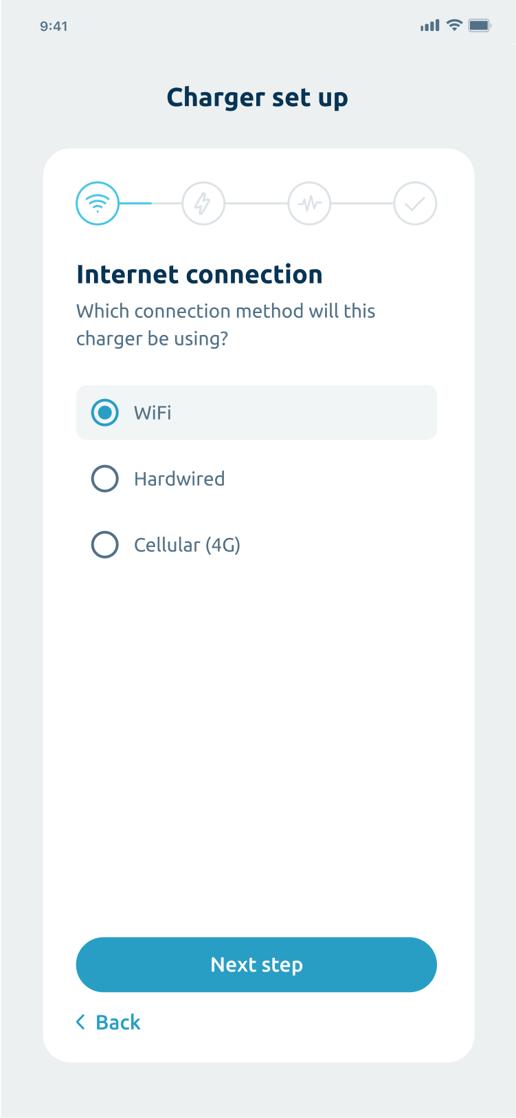
To enable smart functions, the charger must be connected to the internet. There are three connection methods available:

  • Wi-Fi (Recommended)
  • Cellular (4G)
  • Hardwired

For most users, we recommend connecting via Wi-Fi for a balance of convenience and functionality.

Important

Bluetooth pairing and SSID & Password Wi-Fi connection are available on chargers of firmware V11.1.1 or greater. Firmware information can be found on the box.

Wi-fi bluetooth pairing (Recommended)

Power on the charger.

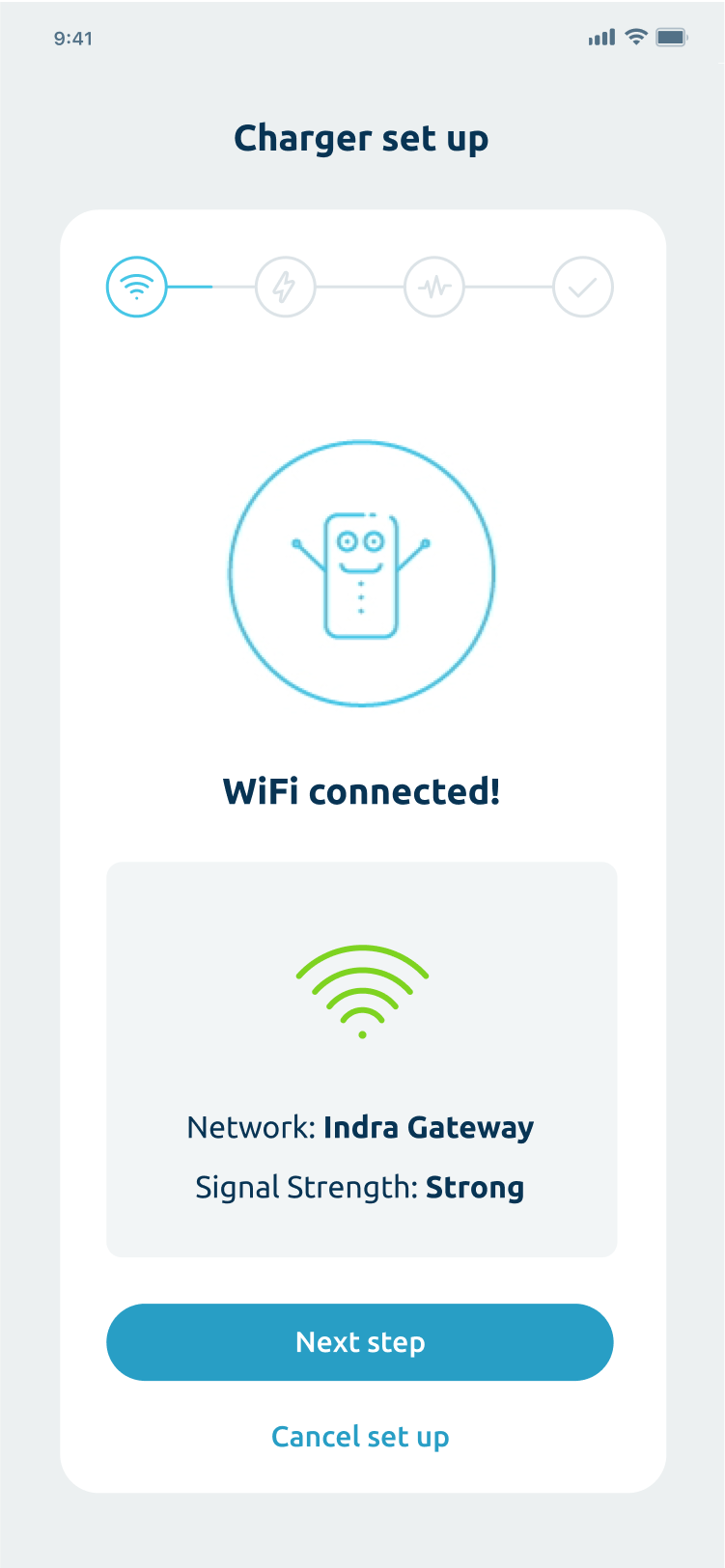
Use the Indra Installer App to connect the charger to the customer’s Wi-Fi network.

  • Follow the prompts in the app to complete the connection process.
  • Once successfully connected, the primary LED on the charger will turn white to indicate the connection is established. You will also see the following screen on the App.

If you're unable to connect to the customer's Wi-Fi via the installer app, follow these steps to connect using WPS mode:

1. Connect the Dongle

2. Enable WPS mode on the router

  • Refer to the router’s user manual for instructions on activating WPS mode.

3. Activate pairing on the charger

  • Press and hold the BOOST button on the charger.
  • Release the button when the LEDs turn orange, but before they turn green.

4. Wait for pairing to complete

The main LED will flash orange while the pairing process is underway.

Once pairing is successful, the main LED will flash green for 5 seconds before returning to white.

Connecting the charger using a 4G dongle

1. Record the WCD number

  • Before starting, make a note of the WCD number located on the dongle.

2. Insert the 4G dongle

  • Plug the 4G dongle into the designated slot in the cable tray.

3. Power on the unit

  • Turn on the charger.

4. Confirm connection

  • Once the connection is established, the primary LED will turn white.

Important

Please note that Indra is not responsible for cellular network availability, which may affect connectivity.

Connect a data cable to the RJ45 socket on the charger from the customer’s router
Once connected the primary LED will go white.

Once the charger is powered up and tested, the charger must be commissioned. Commissioning of the charger is done via the Indra Installer App.

If you haven't already done so, download the Indra Installer App.

Download the Indra Installer App
How to commission using the App

Video: How to commission using the app
Duration: 2 mins 33 secs

Demonstrate the charger functionality

  • Perform a boost charge demonstration If to confirm the customer knows how to use the charger.

Using the Indra App

  • Direct the customer to scan the QR code on the side of the charger to download the Indra App.

Complete the Statement of Compliance

  • Locate the Statement of Compliance provided in the box.
  • Fill it out completely.
  • Provide the completed statement to the customer as evidence of compliance with the Electric Vehicles (Smart Charge Points) Regulations.

Still need help?

Making energy smarter
Join our newsletter
Sign up here to get the latest news, updates and special offers.

This field is for validation purposes and should be left unchanged.
Download your App
crossmenu